AWS Defense in Depth Overview

AWS Defense in Depth Overview

Layers of security bolster defenses for any application, database, or critical data. In a traditional data centers, physical network isolation meant building walls for physical security. For cloud, the providers – AWS, Azure, and others, build the walls, fences and comply with things like ITAR and SOC 1. This is the provider-owned and completely provider-controlled security they provide to users.

Up the cloud stack, users can add and more layers of defense at the virtualization layer by creating logical segmentation, and at the application layer with application segmentation. Three key ways to add network security users can access provider-owned, user-controller features like virtual private clouds (aka VLAN isolation), port filtering, and static assignable public IP addresses.

AWS allow users to control certain features and services, but ultimately own the feature. The cloud user is responsible for setting up, maintaining and updating these features. One example is port filtering on the host operating system. Port filtering prevents packets from ever reaching a virtual adapter. hypervisor firewall through network mechanisms such as security groups or configuration files. Users can limit rules to only allow ports needed for each application.

AWS Defense in Depth

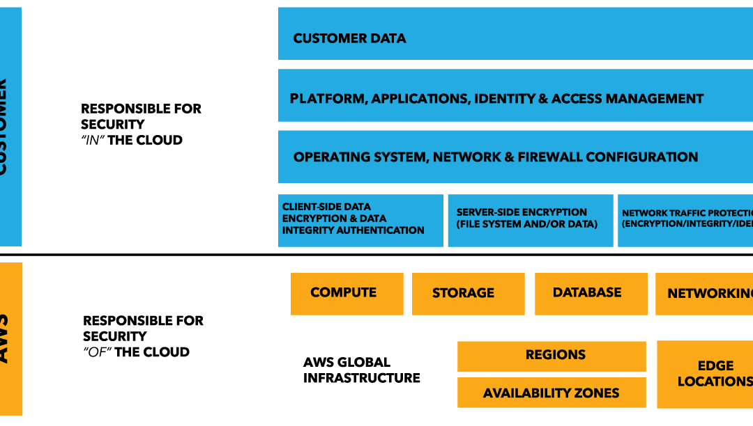
AWS is responsible for security of the cloud. AWS users are responsible for security in the cloud.

Customer data and applications are completely controlled by AWS users. AWS provides security features including IAM, firewalls, port filtering (security groups), and network protection but users must enable, maintain and control those features.

AWS Shared Responsibibility

AWS provider-owned/User Controlled Security

Identity and Access Management (IAM)

In AWS, the identity and access management (IAM) service allows users to create specific accounts for each person/role that needs AWS access.

In a new AWS account, the initial account is the “root account” with full access all services and controls in the account. After configuring the administrator roles and access you should shift all administrative activities in the console to assigned roles. Before deleting the root access key, you can first deactivate it to test for any issues. You can next delete the root account and root access key to prevent any outside access.

Force MFA for all AWS users

From the IAM console, you can add multi-factor authentication (MFA) for all users. First, enable MFA on the root account. Next, you can require all AWS users to configure MFA. The “force MFA” IAM policy is attached to each user. Note that once you enable “force MFA” the user will be denied all other permissions until the he/she sets up MFA and logs in using MFA.

AWS MFA

Use IAM roles for all services

AWS IAM allows you to create roles to give users or AWS infrastructure the necessary permissions to access other AWS services. For example, roles in EC2 roles can limit which users can launch an instance and which S3 permissions can interact with EC2.

AWS Key Management Service

AWS Key Management Service (KMS) is a service for creating and controlling encryption keys. KMS uses Hardware Security Modules (HSMs) to protect keys in AWS.

CloudTrail

CloudTrail is an AWS service that records API calls for you account and delivers log files. CloudTrail is not enabled by default. CloudTrail provides a history of AWS API calls for your account., including API calls made via the Management Console, SDKs, command line tools, and high-level AWS services. CloudTrail API call history enables security analysis, resource change tracking, and compliance auditing.

AWS Config

AWS Config is a managed service that creates a resource inventory, configuration history, and configuration change notifications for security and governance. AWS Config lets you export a complete inventory of your AWS resources with all configuration details. AWS Config helps enable compliance auditing, security analysis, and resource change tracking.

AWS Trusted Advisor

AWS Trusted Advisor inspects the AWS environment and finds opportunities to save money, improve system performance and reliability, or help close security gaps.

Amazon Inspector

Amazon Inspector is an automated security assessment service that can assess applications for vulnerabilities or deviations from best practices. Amazon Inspector includes a knowledge base of hundreds of rules mapped to common security compliance standards (e.g., PCI DSS) and vulnerability definitions.

AWS Networking Security

Security Groups = act as firewalls for inbound and outbound traffic to/from your EC2-VPC devices. Security group characteristics include:

  • By default, outbound traffic is allowed
  • Rules are permissive (you can’t deny access)
  • Add / remove rules at any time
  • You can copy the rules from an existing security group to a new security group
  • Security groups are stateful — if you send a request from your instance, the response traffic for that request is allowed to flow in regardless of inbound security group rules

To create a security group rule, specify the following:

  1. The protocol to allow (such as TCP, UDP, or ICMP)
  2. For TCP, UDP, or a custom protocol: The range of ports to allow
  3. For ICMP: The ICMP type and code
  4. Choose one of the following options for the source (inbound rules) or destination (outbound rules):
  • An individual IP address, in CIDR notation ( 203.0.113./32)
  • An IP address range, in CIDR notation (for example, 203.0.113.0/24)
  • a name or ID of a security group – allow instances associated with the specified security group to access instances associated with this security group

Network access control lists (ACLs) = act as a firewall for associated subnets, controlling both inbound and outbound traffic at the subnet level.
The following are the parts of a network ACL rule:

  • Rule number. Rules are evaluated starting with the lowest numbered rule. As soon as a rule matches traffic, it’s applied regardless of any higher-numbered rule that may contradict it.
  • Protocol. You can specify any protocol that has a standard protocol number. For more information, see Protocol Numbers. If you specify ICMP as the protocol, you can specify any or all of the ICMP types and codes.
  • [Inbound rules only] The source of the traffic (CIDR range) and the destination (listening) port or port range.
  • [Outbound rules only] The destination for the traffic (CIDR range) and the destination port or port range.
  • Choice of ALLOW or DENY for the specified traffic.

* NOTE: ACLs are similar to Security Groups (rules), but ACLs monitor traffic at the subnet level. It’s important to note that Security Groups are Stateful, while the NACL is Stateless. *

Elastic IP address (EIP) = static IP address associated with your AWS account. Use EIPs to mask the failure of an instance or software by rapidly remapping the address to another instance in your account.

An Elastic IP address is a public IP address, reachable from the Internet. If your instance does not have a public IP address, you can associate an Elastic IP address with your instance to enable communication with the Internet.

When you associate an Elastic IP address with an instance in EC2-Classic, a default VPC, or an instance in a nondefault VPC in which you assigned a public IP to the eth0 network interface during launch, the instance’s current public IP address is released back into the public IP address pool. If you disassociate an Elastic IP address from the instance, the instance is automatically assigned a new public IP address within a few minutes.

Further Reading: 10 AWS security blunders and how to avoid them. By Fahmida Y. Rashid Originally published on InfoWorld Nov 3, 2016

Next up, use your user-provided, user-owned features to add application layer security.

Services like SSL/TLS termination, load balancing, caching, proxies, and reverse proxies can also add application-layer security. Additionally, tailoring security policies to each application can be more effective than applying complex, blanket security policies across multiple applications.

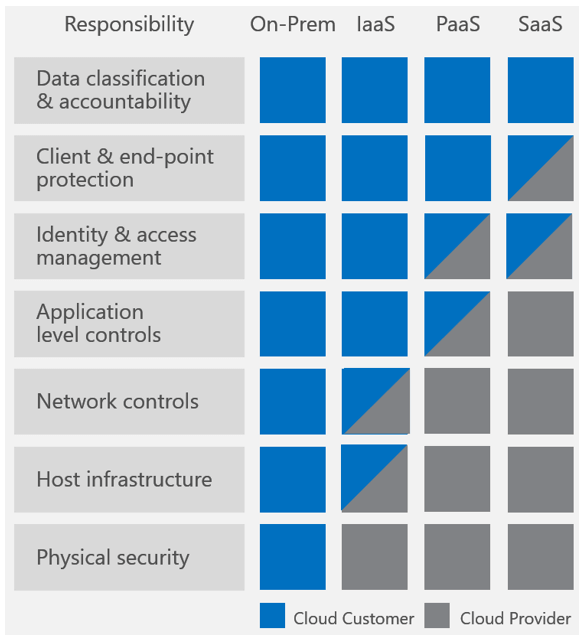
Quick overview of Azure Defense in Depth

Quick overview of Azure Defense in Depth

Layers of security bolster defenses for any application, database, or critical data. In a traditional data centers, physical network isolation meant building walls for physical security. For cloud, the providers – AWS, Azure, and others, build the walls, fences and comply with things like ISO 9000. This is the provider-owned and complexly provider-controlled security they provide to users.

Up the cloud stack, users can add and more layers of defense at the virtualization layer by creating logical segmentation, and at the application layer with application segmentation. Three key ways to add network security users can access provider-owned, user-controller features like VLAN isolation, port filtering, and static assignable public IP addresses.

Public cloud providers allow users to control certain features and services, but ultimately own the feature. The cloud user is responsible for setting up, maintaining and updating these features. One example is port filtering on the host operating system. Port filtering prevents packets from ever reaching a virtual adapter. hypervisor firewall through network mechanisms such as security groups or configuration files. Users can limit rules to only allow ports needed for each application.

In Azure, you can use the following Azure-provided, user-controlled features:

  • Azure Multi-Factor Authentication
  • Privileged Access Workstations (PAW )
  • Azure Role based access control (RBAC)
  • Network Security Groups (NSGs)
  • Azure Key Vault
  • Azure Disk Encryption
  • Security Center monitoring and compliance checking

Azure provider-owned/User Controlled Security

  1. Use Azure identity management and access control for each application (like AD), enable password management and create multi-factor authentication (MFA) for users
  2. Use role based access control (RBAC) to assign privileges to users
  3. Monitor account activity
  4. Add and control access to each Resource

View and Add access to each Azure Resource and Resource group

  • Select Resource groups in the navigation bar on the left.
  • Select the name of the resource group from the Resource groups blade.
  • Select Access control (IAM) from the left menu.

The Access control blade lists all users, groups, and applications that have been granted access to the resource group.

  • Select Add on the Access control blade.
  • Select the role that you wish to assign from the Select a role blade.
  • Select the user, group, or application in your directory that you wish to grant access to. You can search the directory with display names, email addresses, and object identifiers.
  • Select OK to create the assignment. The Adding user popup tracks the progress. After successfully adding a role assignment, it will appear on the Users blade

Azure Networking Security

Azure offers several networking security services:

  • Azure VPN Gateway
  • Azure Application Gateway
  • Azure Load Balancer
  • Azure ExpressRoute (direct connection through ISP)
  • Azure Traffic Manager
  • Azure Application Proxy

More on Network Access Control

Network access control is the act of limiting connectivity to and from specific devices or subnets within an Azure Virtual Network to ensure your VMs and services are accessible to only users and devices you control.

  • Network Layer Control – basic network level access control (based on IP address and the TCP or UDP protocols), using Network Security Groups. A Network Security Group (NSG) is a basic stateful packet filtering firewall and it enables you to control access based on a 5-tuple. NSGs do not provide application layer inspection or authenticated access controls.
  • Route Control and Forced Tunneling – customize routing behavior for network traffic on your Azure Virtual Networks by configuring User Defined Routes in Azure.
    Forced tunneling = ensure services are not allowed to initiate a connection to devices on the Internet. All connections to the Internet are forced through your on-premises gateway. You can configure forced tunneling by taking advantage of User Defined Routes.
  • Network Security Groups = contains a list of access control list (ACL) rules that allow or deny network traffic to your VM instances in a Virtual Network


Next up, use your user-provided, user-owned features to add application layer security.

Services like SSL/TLS termination, load balancing, caching, proxies, and reverse proxies can also add application-layer security. Additionally, tailoring security policies to each application can be more effective than applying complex, blanket security policies across multiple applications.

An intro to Internet Protocol Security

IPsec: Internet Protocol Security

Internet Protocol Security ( IPsec ) is a set of protocols defined by the IETF, to provide IP security at the network layer. IPsec uses cryptographic security services to protect communications over Internet Protocol (IP) networks. IPsec supports network-level peer authentication, data-origin authentication, data integrity, data confidentiality (encryption), and replay protection.

You can use IPsec to protect data between:

  • a pair of hosts (host-to-host),
  • a pair of security gateways (network-to-network),
  • a security gateway and a host (network-to-host).

IPsec is end-to-end, operating at Layer 3 (Network). Only IPsec protects all application traffic over an IP network. Using IPsec networks can ultimately secure applications from the IP layer. For comparison, other Internet security systems operate in the upper layers: Transport Layer Security (TLS) operates at Layer 4 (Transport Layer) and Secure Shell (SSH) at Layer 7 (Application layer).

What is HTTP?

HTTP stands for Hypertext Transfer Protocol. It’s the network protocol used to deliver virtually all files and other data ( called resources) on the Web. HTTP takes place through TCP/IP sockets.

A browser is an HTTP client because it sends requests to an HTTP server (Web server), which then sends responses back to the client. The standard (and default) port for HTTP servers to listen on is 80, though they can use any port.

What are “Resources”?

HTTP is used to transmit resources, not just files. A resource is some chunk of information that can be identified by a URL (it’s the R in URL). The most common kind of resource is a file, but a resource may also be a dynamically-generated query result, the output of a CGI script, a document that is available in several languages, or something else.

Structure of HTTP Transactions

Like most network protocols, HTTP uses the client-server model: An HTTP client opens a connection and sends a request message to an HTTP server; the server then returns a response message, usually containing the resource that was requested. After delivering the response, the server closes the connection (making HTTP a stateless protocol, i.e. not maintaining any connection information between transactions).

The format of the request and response messages are similar, and English-oriented. Both kinds of messages consist of:

  • an initial line
  • zero or more header lines
  • a blank line (i.e. a CRLF by itself)
  • and an optional message body (e.g. a file, or query data, or query output).

Put another way, the format of an HTTP message is:

<initial line, different for request vs. response>

Header1: value1

Header2: value2

Header3: value3

<optional message body goes here, like file contents or query data;

it can be many lines long, or even binary data $&*%@!^$@>

See the full HTTP article at HTTP Made Really Easy

What is an IPsec based VPN?

What is an IPsec based VPN?

IPsec Networks

IPsec is a protocol suite for securing IP (transport layer) communications between peers by authenticating and encrypting each packet of communication.

In the network diagrams, the two red lines represent IPsec tunnels from a VNS3 Controller to the two remote firewall devices. The London and Chicago locations are two different endpoints.

VNS3 overlay network

An IPsec tunnel is built between two endpoint devices that “speak” the network standard. You can think of the following two phases and these two devices cordially introducing themselves and establishing a connection via an appropriately firm and friendly handshake.

IPsec negotiation is divided into two phases:

  1. Introductions: Peers find each other over the internet and trade security parameters
  2. Conversation: Peers exchange information using agreed-upon security standards

What is an IPsec based VPN?

An IPsec based VPN is made up of two parts:

  1. Internet Key Exchange protocol (IKE), underlying port UDP 500
  2. IPsec protocol (ESP), underlying Protocol 50 or if using “nat-traversal” UDP 4500

Basically there is an initial brief interaction where one or each of the devices attempt to discover each other, via the Internet, they then trade Phase 1 (IKE) parameters and attempt to get a Phase 1 (sometimes called IKE or ISAKMP) connection which creates the keys used to encrypt Phase2. They then trade Phase 2 parameters and attempt to create an encrypted Phase 2 (sometimes called IPSec SA or ESP) tunnel connection.

IPsec negotiation is divided into two phases:

Phase 1: Initial negotiation phase. Peers find each other over the internet and trade security parameters in order to create “session keys” that prove they are who they claim to be. This is what security experts call a key exchange, and the peers use the Internet Key Exchange Protocol (IKE) to validate each other’s security claims.

Phase 2: Peers trade Phase 2 security parameters. The peers trust each other, and now can create an encrypted tunnel that connects them using IPsec Protocol Encapsulating Security Payload (ESP) to encrypt the IP Packet. That way, no one else can see what data is traveling between the peers. Even if someone was able to see the data, it is all encrypted and unreadable without a secure key.

How does an IPsec VPN work?

IPsec is able to secure packets as they travel across an IP network, usually between two sites separated by the public Internet. IPsec uses cryptographic security services to authenticate and encrypt each data packet as it travels two endpoints and protects that data from traffic sniffers.

IPsec connections ensure data isn’t read or tampered with when it travels across any type of network. IPsec is especially important when you’re building hybrid deployments between public cloud providers or the public internet.

IPsec has 2 types of implementation: a host-to-host transport mode, or network tunneling mode:

Transport mode
In transport mode, only the payload of the IP packet is usually encrypted and/or authenticated. Transport mode does not change the routing, since IP headers aren’t modified or encrypted. Transport mode works best in host-to-host connections.

Tunnel mode
In tunnel mode, the entire IP packet is encrypted and/or authenticated. Tunnel mode must encapsulated the headers into a new IP packet with a new IP header. VPNs use tunnel mode for network-to-network communications, host-to-network communications, and host-to-host communications. Tunnel mode does support NAT traversal.

Understanding IP Addresses and Networks

Understanding IP Addresses and Networks

IP Addresses

The IP address (Internet Protocol address) is an identifier assigned to each device in a TCP/IP network. Devices use IP addressees to locate and identify the source and destination for packets traveling on the network.

IP addresses are usually written and displayed in human-readable notations, such as 172.16.254.1 in IPv4, and 2001:db8:0:1234:0:567:8:1 in IPv6.

IPv4 addresses are a 32 bit binary addresses. These 32 bits (or 4 bytes) are also called octets, broken up into four sections divided by dots, or periods. Each octet represents a binary (base 2) number between 0 and 28, each octet will be between 0 and 255.

IPv6 addresses are 128 bits, or 16 bytes. While most organizations still use IPv4, all of our devices will eventually run out of address space and IPv6 allows for more addresses. IPv6 addresses are generally written in the following form: hhhh:hhhh:hhhh:hhhh:hhhh:hhhh:hhhh:hhhh, for example: E3D7:0000:0000:0000:51F4:9BC8:C0A8:6420 or in shorthand notation E3D7::51F4:9BC8:C0A8:6420

NOTE: Remember the base 2 and IPv4 networking concepts when you interact with networking topics like subnetting and IP address ranges. For more on octets and IPv4 addresses, read the in-depth article from Cisco and the series from Lifewire.

IP Addresses and Networks

IP addresses tell us both the network segment and the host segment. Within an IP address, you can tell the IP address class and subnet mask.

In the example IP address

192.168.1.1

the network ID is the first 3 octets: 192.168.1. Every host inside the network will have same 3 octets: 192.168.1.2, 192.168.1.3, 192.168.1.4 etc.

The host ID, or .1 in the example, is assigned to the specific address.

Subnet Mask = A subnet (or subnetwork) is a logical subdivision of an IP network. Dividing a network into two or more networks is called subnetting.

To allow for more IP addresses in a network, “Classful” network design allows more individual network assignments. To separate network ID from host ID and classify each IP address in a network, use class to categorize IP address ranges:

  • Class A: 1.0.0.0 – 126.0.0.0 >> localhost
    • Class A Subnet Mask: 255.0.0.0
  • Class B: 128.0.0.0 – 191.255.255.255
    • Class B Subnet Mask: 255.255.0.0
  • Class C: 192.0.0.0 – 223.255.255.0 >> usually your internal network
    • Class C Subnet Mask: 255.255.255.0
  • Class D: 224.0.0.0 – 239.0.0.0 >> Multicast

CIDR Notation for networks

Because “Classful” networking didn’t scale well with the boom of internet-connected devices, the class system was replaced with Classless Inter-Domain Routing (CIDR).

CIDR routing prefixes are expressed as the first address of a network, followed by a slash character (/), followed by the bit-length of the prefix. For example,

192.168.1.1/24

CIDR notation lets you group blocks of addresses into a single routing table entry. CIDR blocks share an initial sequence of bits in the binary representation of their IP addresses (the network ID). To show how large a network is (or how many addresses in that network) you can omit the address portion. A /20 block is a CIDR block with an unspecified 20-bit prefix.

Example 

When you create a VPC in Amazon AWS or a VPN in Azure, you must specify a range of IPv4 addresses; for example, 10.0.0.0/16. [Since IPv6 is still not as common, both clouds offer optional IPv6 addressing.]

The new VPC you created spans the entire AWS region. After you create a VPC, you can add one or more subnets in each Availability Zone. Specify the CIDR block for each subnet. The subnet CIDR block must be a subset of the whole VPC CIDR block. Your subnets can only be in one Availability Zone and cannot span zones. Use separate Availability Zones to protect applications from location failure (by adding high availability).

VPC Network diagram

Network sizing with CIDR notation

Future sections will delve into networking sizing for AWS and Azure, but you will eventually need to calculate your network size using subnet CIDR blocks. A handy tool is Subnet-calculator.com

For example, AWS recommends using a CIDR block of /16 or smaller:

  • 10.0.0.0 – 10.255.255.255 (10/8 prefix)
  • 172.16.0.0 – 172.31.255.255 (172.16/12 prefix)
  • 192.168.0.0 – 192.168.255.255 (192.168/16 prefix)
4 things everyone should know about network layers

4 things everyone should know about network layers

This is a first in a series of posts about networking fundamentals.

At Cohesive Networks we have found that not all VNS3 users are networking experts – and that’s ok! Usually customers come to us to solve a problem. It is usually network related, but not always. We often find that business units or operations teams are looking for a solution to a connectivity or security problem, regardless of how the networking piece fits in.

We’re always here to help. Our award-winning support team helps customers solve problems, but also troubleshoots networking troubles. From misconfigured settings on physical network devices to sneaky cloud set up pitfalls, our team is here to help.

1. the OSI Layers

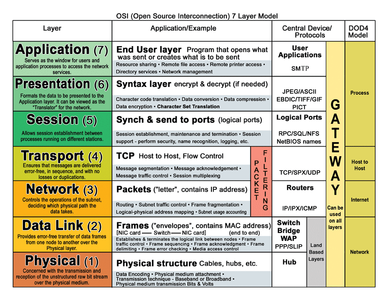
Arguably the OSI layers are foundation for all networking knowledge. The OSI Model (shortened from the Open Systems Interconnection model) evolved in the 1970s and 80s from the early ARPANET and telephone providers. The model describes layers of connectivity and activity based on 7 layers. A similar model, the TCP/IP model is a combined version of the OSI layers.

Essentially, data passes from one connected device to another over a network, from the top of the OSI model down to Layer 1, then back up again to Layer 7. As data passes through each phase, essential functions like encryption and encapsulation occur. Data travels from a software application at Layer 7, down to a router at layer 3, packets bounce between physical hubs at Layer 1, and back up to a router on the other side’s Layer 3, then finally up to a connected application on Layer 7.

OSI-layer-model

How can you remember “Physical/Data Link/Network/Transport/Session/Presentation/Application” in the Layer 7 OSI model? How about “Please Do Not Teach Students Pointless Acronyms.”

2. Packet Switched networks

Packet switched networks are characterized by how they exchange data. Packets , or discreet units of data, are transmitted between devices in a network. Packet switching improves network efficiency and enables more device to communicate reliably on a network.

Packets are made up of “headers” and “payloads” The header contains information about the packet’s destination. Networking devices use the header to direct the packet toward its destination. Once it reaches the final destination, the payload is extracted and used by application software.

Packet-switched networks are generally better because they can transfer data bit by bit, as opposed to a firehose of data. That way, receiving parties can confirm delivery and ask for data to be resent if needed.

3. Hubs vs Switches vs Routers

Hub = Layer 1 (Physical) carry electricity, essentially, hubs send information to all other ports as electricity to everyone connected on that hub.

Switch = Layer 2 (Data) uses packet switching to receive, process, and forward data. A switch, like a hub, carries data from port to port, but a switch keeps a record of MAC addresses of all the devices attached to it.

Router = Layer 3 (Network) directs packets from a source to the destination using specific packet forwarding mechanisms. Routers only send data to other routers using IP addresses. A key difference between a router and a switch is the level of information the device “knows” about the traffic. Switches only look at the Link Layer address, not the IP datagram (or message).

Bonus term:
MAC address = unique identifier assigned to network interfaces for communications at the data link layer of a network segment.

Back to the 7 Layer OSI model – you can determine what tools are appropriate and what data can be manipulated by each layer. For devices, a handy rule of thumb: any data at layer 3 must interact with a router. Data at layer 2 must interact with a switch. Data at layer 1must interact with a hub.

4. Networking at home vs. networking in the cloud

At home, your router connects you to the ISP Network (gateway). A gateway is a term to describe a connection of 2 or more networks connections.

Inside your home, the gateway is between your internet service provider (ISP) network and your network. You have a public IP address given to you by your ISP and an internal one created by your NAT. More on NAT in future posts…

A home router also acts as a Switch for communicating between devices inside your home network. If your network is slow whenever there are more people on the network, your router is likely acting as a hub also. Remember, hubs send data to all devices on a network.

“So when your home router says it’s actually a hub / switch / router — it really is a hub/switch/router.” Want more network layer fun? Read the full article from Louis Cremen: 10 things InfoSec professionals need to know about networking

Bonus: How encapsulation works at the OSI network layers